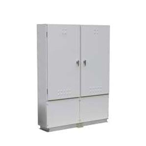
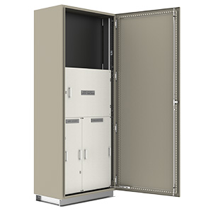
Order Guide
| Part Number | Description | CT Chassis Rating | Test | Height (mm) | Width (mm) | Depth (mm) |
|---|---|---|---|---|---|---|
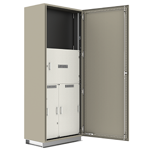
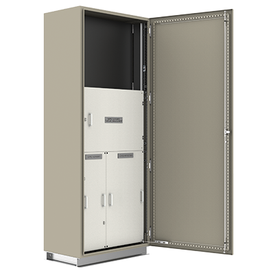
| SMB1/15 | Cabinet supplied with meter and consumer panel (ex VIC) | 630A | 36kA for 1 sec | 2075 | 800 | 500 |
| SMB1/15/S* | Cabinet supplied with meter and consumer panel (ex VIC) | 630A | 36kA for 1 sec | 2075 | 800 | 500 |
| Part Number | Description | Height (mm) | Width (mm) | Depth (mm) |
|---|---|---|---|---|
| CTB/E2 | Cubicle empty fitted with 3 x 32A HRC fuses (holders only), weatherproof. To suit CTC200/400A and CTC/630A. Available in Light Grey RAL7035. | 500 | 720 | 340 |
| Part Number | Description | CT Chassis Rating | Test | Height (mm) | Width (mm) | Depth (mm) |
|---|---|---|---|---|---|---|
| CTC200/400A | CT chassis for S-Type CTs | 200/400A | 25kA for 1 sec | 500 | 400 | 95 |
| CTC630A | CT chassis for T-Type CTs | 630A | 36kA for 1 sec | 500 | 400 | 120 |
Accessories
| Part Number | Product | Description |
|---|---|---|
| CTPFK | Potential fuse kit | Potential fuse kit with cover for sealing and insulating baseplate (excludes fuses) |
| LKDCT10016 | QLD Meter Isolation Link, with link, clear | |
| LKDVA10000 | Authority CT Metering Block, with Z links | |
| LKDVA10001 | Authority CT 200/5 Extended Range, S-type, each | |
| LKDVA10002 | Authority CT 800/5 Extended Range, T-type, set of 3 | |
| LKDVF10000^ | NSW fuse holder only, 30.2x58mm, w. Barrier | |
| LKDVF10002 | Standard 100A fuse holder only, 22x58mm, clear |
AS/NZS 61439 Compliance
AS/NZS 61439 is the new series of standards for low-voltage (LV) switchgear and control gear assemblies. For more information on whether you need to comply see our AS/NZS 61439 page.
Click the bar below the requirements and responsibilities for complaince with AS/NZS 61439 for this enclosure.
The following definitions apply to this table: -
- Original Manufacturer* - Switchboard designer and manufacturer of the switchboard enclosure.
- Assembly Manufacturer* - A switchboard builder.
- Original Equipment Manufacturer - The company who manufactured the switchgear used in final assembly.
*The original manufacturer and assembly manufacturer can be the same company or different companies.
If you are a SWITCHBOARD BUILDER this means you are the ASSEMBLY MANUFACTURER and you may be the ORIGINAL MANUFACTURER too. Any switchgear you order will need to be covered by the requirements of the Original Equipment Manufacturer.
B&R has some (but not all) of the responsibilities of the ORIGINAL MANUFACTURER.
If you are an END USER of the equipment you can see who has responsibility from these definitions.
| No | Characteristic to be Checked | Clause | Responsibility | Comments |
|---|---|---|---|---|
| 1 | Strength of material and parts: | 10.2 | ||
| Resistance to corrosion | 10.2.2 | Original Manufacturer | The resistance to corrosion was tested using a representative sample. Report; 103687. |
|
| Thermal stability (relates to non-metal enclosures) | 10.2.3.1 | Original Manufacturer | This clause refers mainly to plastic enclosures. | |
| Resistance to abnormal heat and fire (due to internal electric effect) | 10.2.3.2 | Original Manufacturer | All insulating materials supplied have been tested to 960ºC glow-wire Standard. Plus ES report; 103863 |
|
| Resistance to ultra-violet (UV) radiation | 10.2.4 | Original Manufacturer | UV ratings refer mainly to plastic enclosures however metal Powder-coat painted enclosures incorporates UV stabilization. AksoNobel report; 20LSR178 | |
| Lifting | 10.2.5 | Original Manufacturer | Lifting is verified by test, if required. Generally this relates to larger switchboards to which lifting means (lugs) have been provided. Plus ES report; 103687 |
|
| Mechanical Impact | 10.2.6 | Original Manufacturer | IK10; Metal enclosure systems have been tested to exceed IK10 (20 Joules). | |
| Marking | 10.2.7 | Assembly Manufacturer | Markings must be verified by test. Tests are performed by rubbing with water and petroleum spirits; generally done by the Switchboard Builder (Assembler). | |
| 2 | Degree of protection of enclosures (IP) | 10.3 | Original Manufacturer | IP66; Ingress Protection (IP) rating needs to be verified by test or by assessment. Plus ES report; 103687 |
| 3 | Clearances | 10.4 | Assembly Manufacturer | Clearance and creepage can only be verified by test. Switchboard Builders (Assembler) must maintain compliance by ensuring correct clearance and creepage distances are maintained at >8mm (Uimp=8kV) and >16mm (Ui=1kV) respectively. |
| 4 | Creepage distances | 10.4 | Assembly Manufacturer | |
| 5 | Protection against electric shock and integrity of protective circuits | 10.5 | ||
| Effective continuity between the exposed conductive parts of the ASSEMBLY and the protective circuit | 10.5.2 | Assembly Manufacturer | Equipotential protective earth bonding points are required to be verified by test to less than 0.1ohm. Similar enclosure designs have been tested by Plus ES report; 103687 | |
| Short-circuit withstand strength of the protective circuit | 10.5.3 | Original Manufacturer | Protective circuit verification can be by test or comparison with a reference design. Plus ES report; 104014 |
|
| 6 | Incorporation of switching devices and components | 10.6 | Assembly Manufacturer | Points 6, 7 and 8 are largely the responsibility of the Switchboard builder (Assembler). It is a requirement that the Assembler follow guidance from the original manufacturer. The advice of original manufacturers such as B&R and switchgear manufacturers, needs to be adhered to. Switchboard Builders need to be aware of the StandardÂ’s requirements for these verification points and incorporate these into complete design verification documentation. |
| 7 | Internal electrical circuits and connections | 10.7 | Assembly Manufacturer | |
| 8 | Terminals for external conductors | 10.8 | Assembly Manufacturer | |
| 9 | Dielectric Properties | 10.9 | ||
| Power-frequency withstand voltage | 10.9.2 | Original Manufacturer | Dielectric properties generally need to be tested but Impulse withstand can also be calculated. Plus ES report; 104014. | |
| Impulse withstand voltage | 10.9.3 | Original Manufacturer | ||
| 10 | Temperature-rise limits | 10.1 | Assembly Manufacturer | Temperature-rise can be determined by test, comparison or by calculation. Testing conducted under worst case configuration show that the switchboard can operate at a maximum rated current (InA) of 490A. B&R cert. CT-22-10002. Alternatively, AS/NZS 60890 may be used by switchboard designers to determine switchboard ratings not exceeding 490A. |
| 11 | Short circuit withstand strength | 10.11 | Original Manufacturer | Enclosures with a fault rating greater than 10kA need to be 61Compliant. Verification can be by test or comparison with a reference design. Plus ES report; 104014. |
| 12 | Electromagnetic compatibility (EMC) | 10.12 | Original Equipment Manufacturer | Equipment installed in switchboards shall comply with the immunity requirements of the relevant product or generic EMC standard. The Switchboard builder (assembler) shall obtain from the device and or component manufacturer the specific performance criteria of the equipment based on the acceptance criteria given in the relevant standard. |
| 13 | Mechanical operation | 10.13 | Original Equipment Manufacturer | This verification testing need NOT be done on devices already been type tested according to their relevant product standard. Only if their mechanical operation has been modified does the assembly need to be retested by cycling it 200 times. |

